# Level 2-4 Content Requirements for 3D Data
There are several things to take into consideration when preparing 3D data for the Rubens Configurator. This article will explain the process how the meshes are used in the configurator and what the process to convert them is.
If you are not able to willing to deliver the 3D meshes by yourself, you can use services of our partner companies to create or convert your data. If this is the case, feel free to contact your Roomle representative.
# Converting Meshes for Rubens Platform
This is a quick of the detailed summary of the Level 2 Configurators Meshes Conversion and Upload, which will be helpful for understanding of further parts of this chapter.
- Import all meshes into a Blender scene by batch importing
- Apply transforms on all meshes
- Check mesh names
- Export every mesh to a separate OBJ file using the Roomle Blender Addon, with a good file name prefix
- Zip resulting folder and upload to Rubens Admin
- Use the resulting TXT to get the
AddExternalMeshfunctions for thegeometryscript and apply necessary transformations and material stored in the Rubens Admin database - Check material mapping, size, pivot and orientation
This brings following requirements for the meshes.
# Requirements for 3D Meshes
# 1. Format
Mesh format must be importable to Blender. Although there are some more, the formats of high preferences are:
OBJ
FBX
glB
Our process does not support CAD or drawing formats, like DWG, DXF, STEP etc. This is due to the fact that those formats are intended to support manufacturing data. Meshes for 3D visualisation are basically different data.
However, such data can be useful for the content creator in cases where the products are complex and made from separate parts. Such data are very good for reference of placement, dimensioning etc. Please contact the content creators or their project manager to find out which format is optimal for reference.
# 2. Mesh origin
Although this is not common, it matter where the mesh is placed in the coordinate system and what is its orientation. Rubens configurator will finally place the mesh to the center of the scene by center of the base of its bounding box, so that it is placed in front of the camera on the floor plane. However, if there are more meshes to be connected, e.g. by docking components together, the placement of the mesh is essential, so that there is a good fit between the meshes. Therefore, the origin point of the mesh should be placed correctly:
- at the center of the bottom base of the mesh
- at the center of the rear lower edge of the mesh, for products that are to be placed at a wall on the floor
- at the axis of symmetry or plane of symmetry
- at a different point
One concrete rule can not apply here and this is best to be defined in the project analyses phase by the content scripter or analyst.
# 3. Mesh orientation and coordinate system
Rubens Configurator uses a left handed Z-up coordinate system. X axis points to the right, Y axis forward the camera and Z axis up.
The configurator camera will be looking at the object from a {-x, +y +z} direction. It is therefore important, that the mesh is oriented like this. For example, a chair should have its backrest parallel to the X axis, with front side facing the +Y direction.
Coordinates of the meshes will be baked into vertex coordinates (in the step 2. of the conversion process).
# 4. Mesh names
Meshes will be uploaded to the Rubens Admin catalogue under the id which is derived from the mesh name. Format is a catalogueId:productname_meshname. Note, that this is not the file name of the 3D file, but actual name of the mesh inside the file. Therefore is critical that within a product, all meshes have an unique name. Omitting this will lead to extra efforts and project costs and will break content if there are some updates, fixes or mesh redeliveries in the future.
Product name is a prefix selected by the content creator in step 4 of the conversion process. This can be changed between reimports by adding e.g. a v2 to the prefix in order to distinguish different deliveries.
The names must be descriptive, because the content scripters will refer to them by its name. It brings extra efforts to them if the names are random, just numbers, etc. Mesh names should not contain special, incl. language specific characters, spaces and colons. It is recommended to only use simple letters without diacritics, numbers and underscores.
# 5. UV scaling
It is common that one material is applied to different meshes in different product lines and also to primitives. In order to have an invariant and being able to have one material library for the whole product range, there is a convention in the Rubens Configurator platform that the UV scaling unit is 1 milimeter and the texture UV sizes are also defined in milimeters. Therefore, a small cutout of a fabric can be applied universally to any mesh. See details how to achieve this in the UV Scaling (opens new window) chapter.
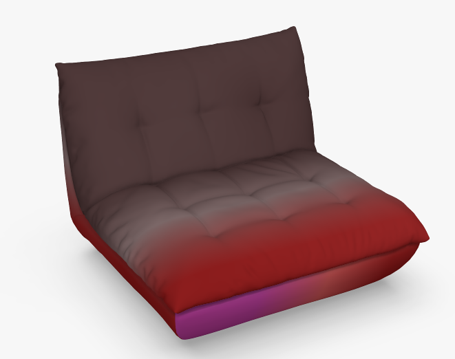
If a reference grid texture of 800 x 800 mm UV size is applied to a sofa mesh in the following example and mesh has standard UV sizing, it will look somehow like this:
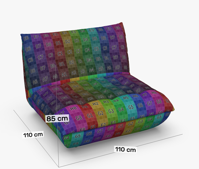
If the UV sizing of the mesh is in milimeters, it will look like following. Given the fact there are 8 x 8 squares in the texture, implicating one square is 100 x 100 mm big and the mesh width is 1100 mm, there should be around 11 squares in the width.
# 6. Texture locations
The materials and textures are not taken from the 3D file, even if the format (like fbx or glb) supports them. They need to be setup in the Rubens Admin interface separately and then applied to the mesh by using the SetObjSurface(materialId) function.
# 7. Separate meshes that have different materials
As a standard convention, one mesh can have only one material applied. If a part of the mesh should carry a different material than a rest, it needs to be separated as another mesh, in accordance with point 4 of those requirements the separated mesh must have an unique descriptive name.
# 8. Assembling the mesh parts
If a 3D file contain mulitple meshes representing more parts, they should be aligned together to fit well.
# 9. Overall mesh sizes
There can be a difference between the size of the mesh bounding box and the product reference size. This is especially true for soft upholstered products, like cushions, armchairs, sofas, etc. This topic is described in the separate chapter further in this document.
# Mesh Size vs. Product Size
The configurator shows the overall product dimensions. Those dimensions can differ from the mesh size by being smaller or bigger in cases of soft upholstered products or in cases where the mesh has some accessories attached. Let's explain this situation on a model of a modular sofa system.
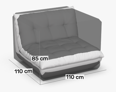
Product size of the sofa module is 110 x 110 x 85 cm.
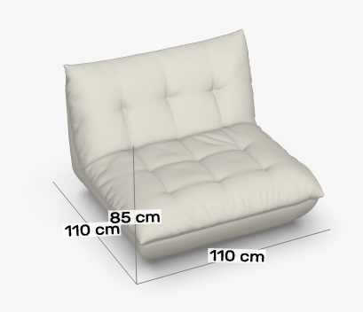
The configurator should therefore display those dimensions. Therefore it can be thought that this also needs to be the bounding box size of the mesh, but that is not true. This stops working when more of such sofa elements have to be placed next to each other. In order to show the correct measurements, which is twice in width (220 x 110 x 85 cm), the models need to be placed in a way that their originas are 110 cm apart. If the bounding box of the mesh is equal to the product reference size and the product is "soft and fluffy", there will be a smaller or bigger gap:
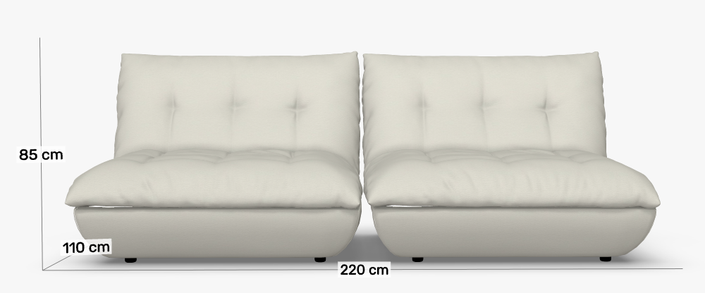
The right solution is to stretch the mesh over the reference dimension box. This will result that the mesh will be bigger.
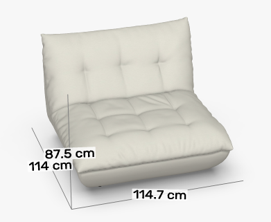
In order to achive the right dimensioning in the configurator, the scripters will override the dimension box as described in the Dimensioning chapter. In the following image, the mesh of 114 x 114.7 x 87.5 cm is used. Along with it, the setBoxForDimensioning function is used to override the reference dimensions to 110 x 110 x 85 cm. The transparent gray box displayed in the image has this reference dimension.
This will also result in closing the gaps by introducing a small overlap in the meshes, like it is visible in the following image:
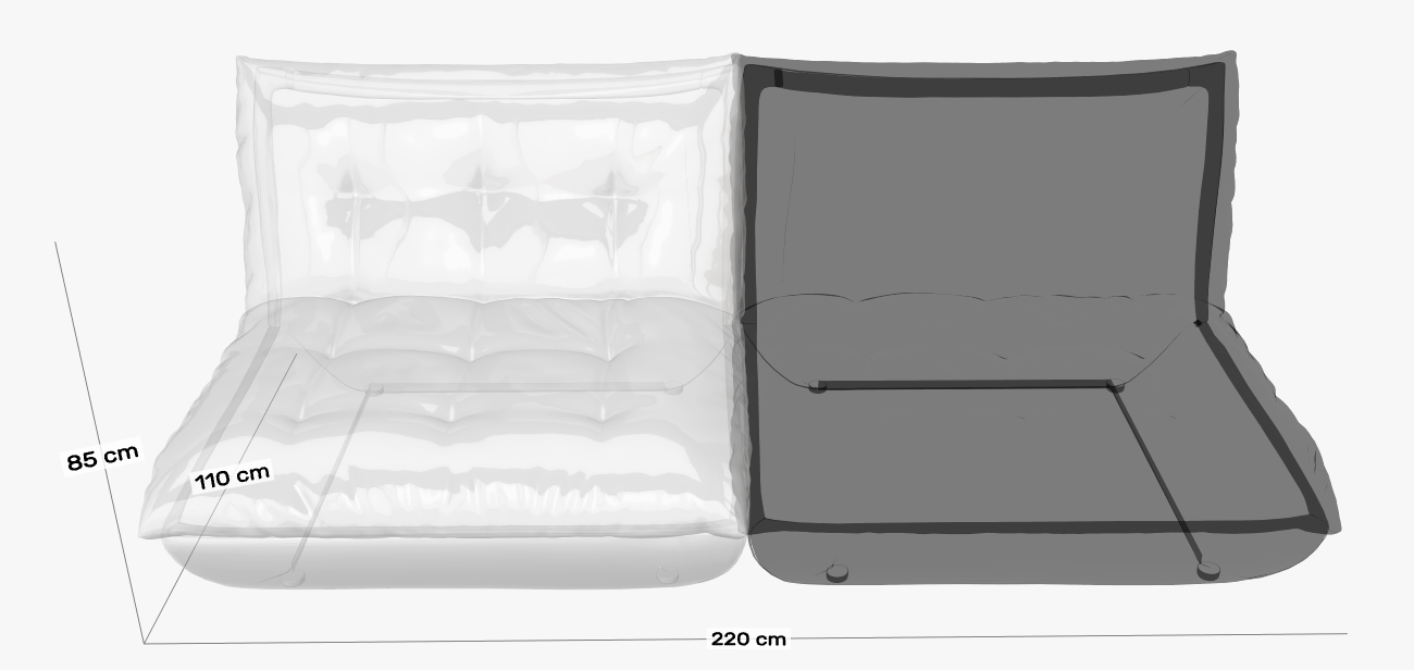
How big the overlap should be is to be defined by the configurator client.
# Origin of meshes in dockable configurators
The meshes should be placed in the coordinate system in a way that it is easy to manipulate them by their pivot points. This is expecially true for upholstered products, where the scripters have high efforts to do any fine adjustments, because they need to find the correct numeric coordinates for placement.
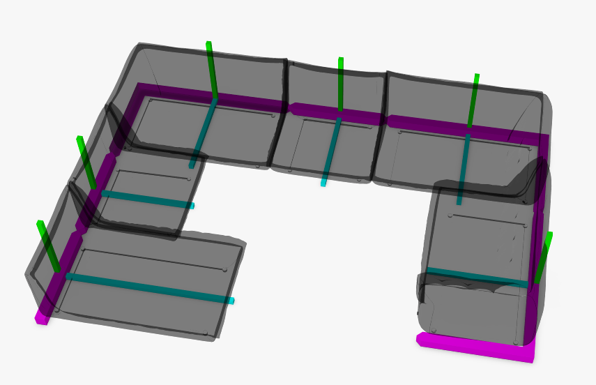
If the product is a sofa system, a good conention for placing the pivot points is in a way that the backrests are aligned together. It is intended, that the scripter then places neighbouring modules by moving them by the product reference size. In the following image, a virtual connection line is drawn in the magenta colour and a good example of the mesh pivots are displayed. The pivot points are placed in the middle of the virutal connection line in every module.
